Know more about BMUs
Building Maintenance Unit (BMU)
As per each building's construction, BMU is a kind of designed crane to make access to the facades of high rising buildings to fulfill façade maintenance and cleaning.
Façade cleaning and maintenance includes:
Cladding, Painting, Glazing, Plastering, Spray Coating, Concrete Repair, High Pressure Cleaning, Sealing, Sandblasting, Inspection & Maintenance
BMU has variety of designs for better and safety performance. It mainly has winch series, climbing series and slide type.
Brodocs provides BMU designed and produced as per project requirement. Our engineer teams and China manufacture are both many-year experienced and reputable in this field. We can assure you that our machinery can keep your building clean and attractive.
• This temporarily installed suspended access equipment's are conforming to the national standard GB19155-2003.
Breif Description About Cradles Job
The temporarily installed suspended access equipment is multipurpose, highly efficient construction machinery applicable to work at heights and ideal equipment for building facade construction, decoration,cleaning and maintenance of high-rise buildings.
Main Structure &Operation Principle.
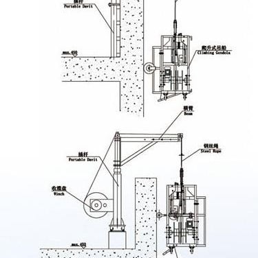
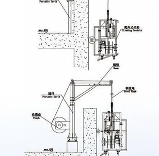
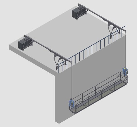
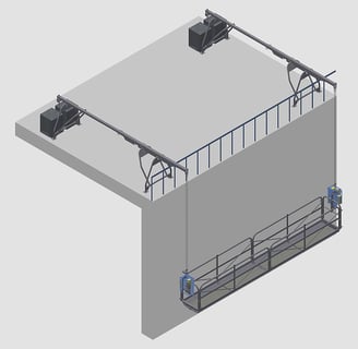
The temporarily installed suspended access equipment consists of the components such as: hoists, safety locks, electric control system, suspended platform, suspension mechanism, counter weight, steel rope, etc. (see figure 1).
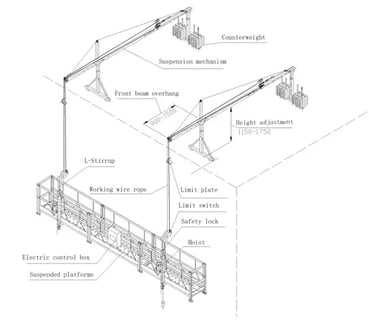
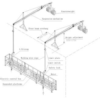
FIGURE 1: Temporarily Installed Suspended Access Equipment
Suspension Mechanism :
•The suspension mechanism is the heavy-duty steel frame structure fixed on the top of the building as the supporting equipment. It is mobile, adaptable and easy to erect and dismantle.
•The suspension mechanism (see figure 2 as below) consists of front beam (1), middle beam (4), rear beam (5), front base (2), rear base (6), upper column (8), tommy bar (3), counter weight(7) and reinforce steel rope (9) etc. The tommy bar is mounted on the front and rear base; the front and rear beams will be fixed through the tommy bar, the middle beam is fixed between the front and rear beam. The upper column is mounted on the tommy bar for fixing the reinforced steel rope and counter weight will be placed on the rear base. For details of structure, see attached figure 1: suspension mechanism.
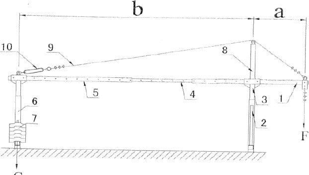
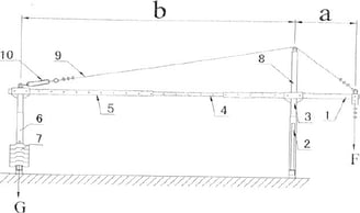
FIGURE 1: Suspension mechanism
The configuration of the suspension mechanism shall meet the following formula:
n = G*b\ F*a
• n------- Safety coefficient against overturning;
• G------ Weight of counter weight in kg;
• a------- Front beam overhang in m;
• F------- Total weight in Kg of the platform, hoists, electric control system, safety lock,
steel rope and rated load, plus wind pressure;
• b------- Distance in m between the front base and rear base.
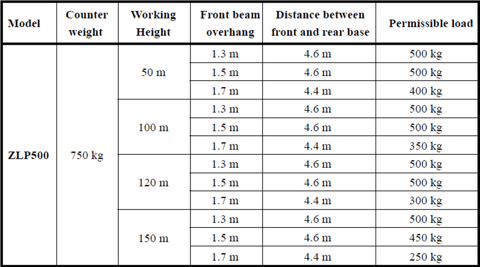
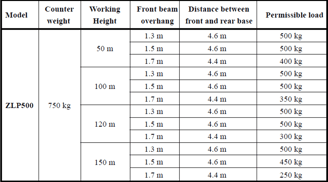
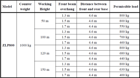
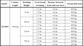
Table 1: The Relation between Permissible Load and the variables as Working Height, Front Beam Overhang,
Distance between the Front Base and Rear Base
Table 2: The Relation between Permissible Load and the variables as Working Height, Front Beam Overhang, Distance between the Front Base and Rear Base.
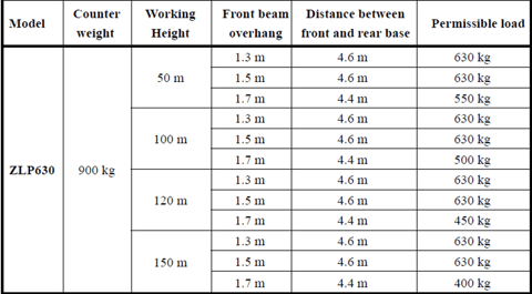
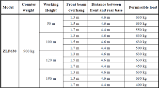
Table 3: The Relation between Permissible Load and the variables as Working Height, Front Beam Overhang, Distance between the Front Base and Rear Base.